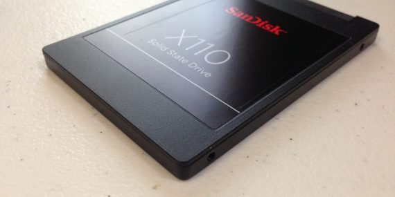
The Genesis of SSDs In the world of data storage, the Solid State Drive (SSD) has emerged as a groundbreaking technology, but how did it all begin? Contrary to popular belief, the history of SSDs doesn’t coincide with the rise of the personal computer era in the late 20th century. The concept of SSDs was,…
Read More
The 7,6 mm Avtomat Kalashnikova model 1947 (Russian: 7,62 мм автомат Калашникова образца 1947), known in English as the AK-47, is a gas-operated assault rifle chambered for the 7.62 x 39 mm cartridge. It was developed in the Soviet Union in the 1940s by the small-arms designer Mikhail Kalshnikov and is named after him. The…
Read More
Invented in 1969, Gore-Tex is a fabric that is both waterproof and breathable at the same time, thanks to a special membrane that will repel liquid water while allowing water vapour to pass through. Gore-Tex is a registered trademark of W. L. Gore & Associates. The generic term for the material is expanded PFTE (ePFTE),…
Read More
The Franklin stove was invented by Benjamin Franklin in 1742, but did not become a commercial success until it had been improved by David Rittenhouse. The Franklin stove was a metal-lined fireplace which had a hollow baffle near the rear to transfer more heat from the fire to the air of the room. With his…
Read More
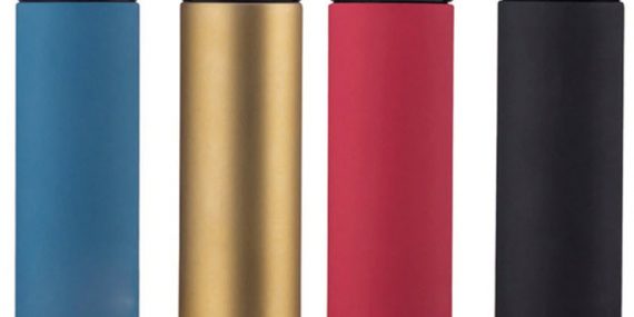
In 1892, the Scottish scientist Sir James Dewar invented the insulating vacuum flask while researching cryogenics. He was performing experiments to determine the specific heat of the element palladium and needed to keep the palladium at a stable temperature. To this end, Dewar enclosed a brass chamber in another chamber and evacuated the air between…
Read More
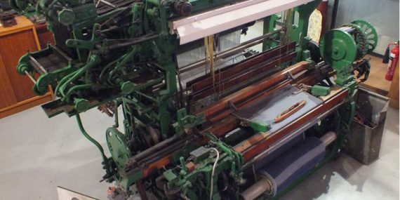
The Northrop Loom was a fully-atomatic power loom introduced in 1894-1895. It is named after James Henry Northrop who invented its shuttle-charging mechanism. The Northrop Loom was marketed by George Draper and Sons, a company based in Hopedale, Massachusetts. With the Northrop loom, the textile industry could achieve higher levels of production, and the loom…
Read More
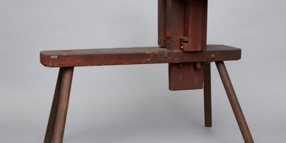
The Shaker broom vise was invented in a time when the standard broom was round. The shaker broom vise resulted in a broom that was flat instead of round, and these flat brooms proved to be more suitable for cleaning purposes. The flat-broom design also revolutionized the production of brooms, and in New England, the…
Read More
What is Imagineering
A portmanteau of “imagination” and “engineering”, the term imagineering denotes creative engineering – turning creative ideas into practical reality.
The term was coined by the Alcoa Corporation around 1940, and later rose to fame through Walt Disney Imagineering, the design and development arm of The Walt Disney Company responsible for the creation of Disney´s theme parks.
Origins and prevalence
Today, the term imagineering is strongly associated with the Walt Disney Company, and Disney Enterprises even trademarked the word in 1990. It is, however, not a word invented by Disney. The earliest known use of the term is from around 1940, when the Alcoa Company began including it in their advertising. From there, it spread, and it appeared in numerous print publications throughout the rest of the 20th century, in texts pertaining to a wide range of different disciplines, including futures studies, urban design, evolutionary economics, geography, politics, and corporate culture.
Alcoa
Alcoa (an acronym for Aluminum Company of America) is an aluminium producer with roots going back to the 1880s. Today, it is the world's eighth-largest producer of aluminum, and conducts operations in ten different countries. During World War II, Alcoa created in international “Imagingeering” program to encourage innovative uses of aluminium.
This is an ad published in Time magazine on February 16, 1942:
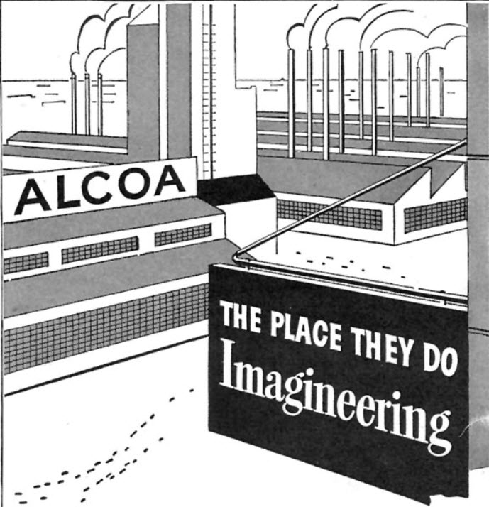
“For a long time we've sought a word to describe what we all work at hard here at Alcoa (...) IMAGINEERING is the word (...) Imagineering is letting your imagination soar, and then engineering it down to earth.”
Other examples
-
In 1942, the October 24 issue of The New York Times included an article titled “Christian Imagineering”.
-
A 1944 Oxford English Dictionary entry cites an advertisment in the Wall Street Journal where the word is included.
-
The artist Arthur Radebaugh used the term to describe his own work, according to the article “Black Light Magic” published in the Portsmouth Times, Ohio, 1947.
-
In 1957, an article written by Richard F. Sailer for the National Carbon Company Management Magazine was published with the headline "BRAINSTORMING IS IMAGINation enginEERING". It was later reprinted by the Union Carbide Company.
-
In 1967, WED Entrprised applied for a trademark for the term.
-
In 1981, Serge King´s book “ Imagineering for Health: Self-Healing Through the Use of the Mind” was published by Quest Books.
What is the Imagineering Foundation?
Founded in 1999, the Imagineering Foundation is an educational charity organization that encourages school children aged 8-16 to engage with engineering and the STEM subjects. The Imagineering Foundation organizes around 150 engineering clubs for children, and in an average week circa, 1 800 children take part in the clubs. Most of the Imagineering clubs are in England, but there are also some in Scotland and Wales.
The Imagineering Foundation was established in England by a group of Midlands engineers and is based in Kenilworth, Warwickshire. In addition to their offline activities, the Imagineering Foundation has created a website where teachers and tutors can access project material, and the organization is also publishing a magazine called The Imagineer.
The organization hosts children's engineering fairs at the Royal International Air Tattoo at RAF Fairford, at the Royal Bath and West Show, and the International Air Day at RNAS Yeovilton.
Is the video game developer Imagineering still active?
No, it was folded into Absolute Entertainment in 1992, and Absolute Entertainment went bankrupt in 1995.
Imagineering was established in New Jersey in 1986 an in-house studio of Absolute Entertainment. Examples of video games they developed for Absolute Entertainment are Battle Tank, Super Battletank, A Boy and His Blob: Trouble on Blobolonia, and The Rescue of Princess Blobette. They also developed games for several third-party publishers, including the Atari Corporation and Activision.
Is the Forex broker Imagine FX still active?
No. The Forex broker Imagine FX has closed down and in no longer in business. They were unregulated and closed down after allegedly scamming a large number of clients. Imagine FX is a good example of why traders should always choose a regulated Forex broker that is regulated by a trusted regulatory body. Click the link to find a list of regulated brokers that is a better alternative than Imagine FX.
Is the magazine ImagineFX still available?
Yes. The magazine ImagineFX is still being published in the UK.
Is the computer company Imagineering Australia still in business?
No, it was sold to First Pacific in 1990 and then merged with Tech Pacific under the Tech Pacific banner. In 2005, Tech Pacific merged with Ingram Micro. Ingram Micro is still active.